
9 Pin Vga Pinout Hot Sex Picture
The 1984 Professional Graphics Controller used a DE-9 connector (the same connector as MDA, CGA and EGA) with analogue signals compatible with those used later by VGA. A similar 9-pin connector was used by 32-bit Acorn computers in the late 1980s. It appears also to have found its way onto some PC video cards, as it is documented on various websites as "9-pin VGA".
Dvi D To Vga Pinout Diagram
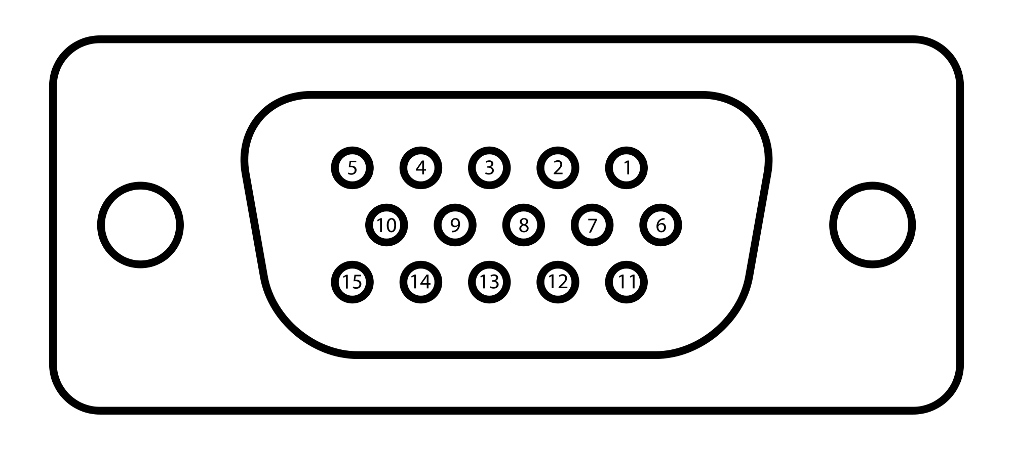
VGA connector pinout This pinout diagram example showing a VGA connector (as viewed from the socket) was redesigned from the Wikimedia Commons file: DE15 Connector Pinout.svg. [commons.wikimedia.org/ wiki/ File:DE15_ Connector_ Pinout.svg] "A Video Graphics Array (VGA) connector is a three-row 15-pin DE-15 connector.
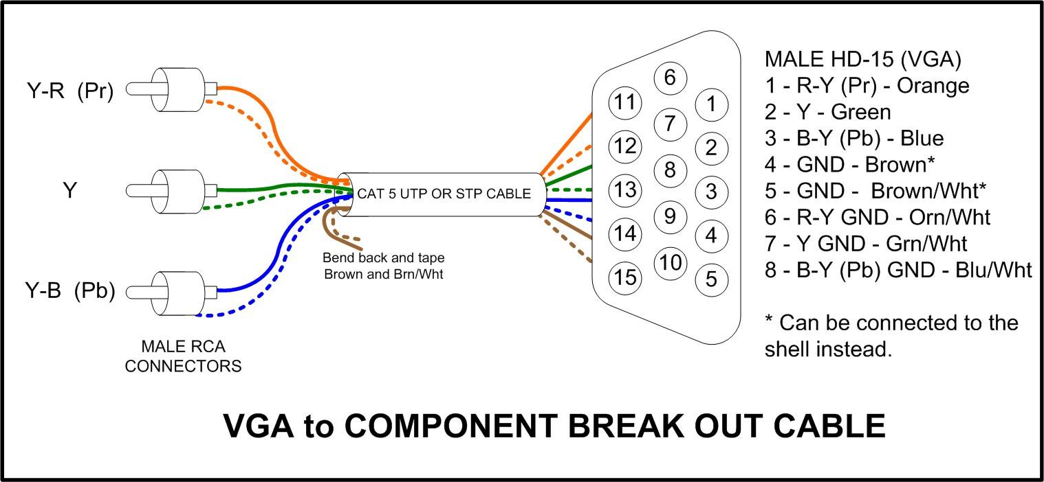
Wiring Diagram Vga To Rca Wiring Diagram Schemas
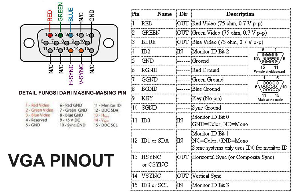
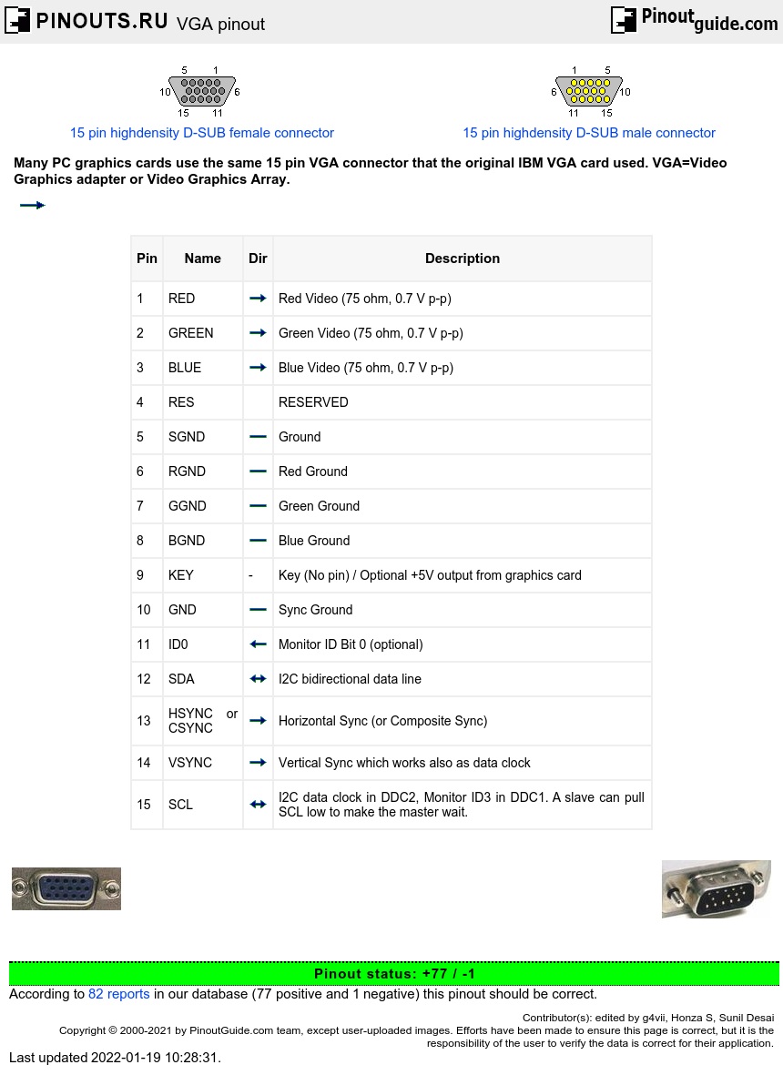
There are at least four versions of the VGA connector, which are the three-row 15 pin DE-15 (also called mini sub D15) in original and DDC2 pinouts, a less featureful and far less common 9-pin VGA, and a Mini-VGA used for laptops. The image and below table are the newer 15-pin VGA VESA DDC2 connector pinout. VGA DDC2 connector pinout:

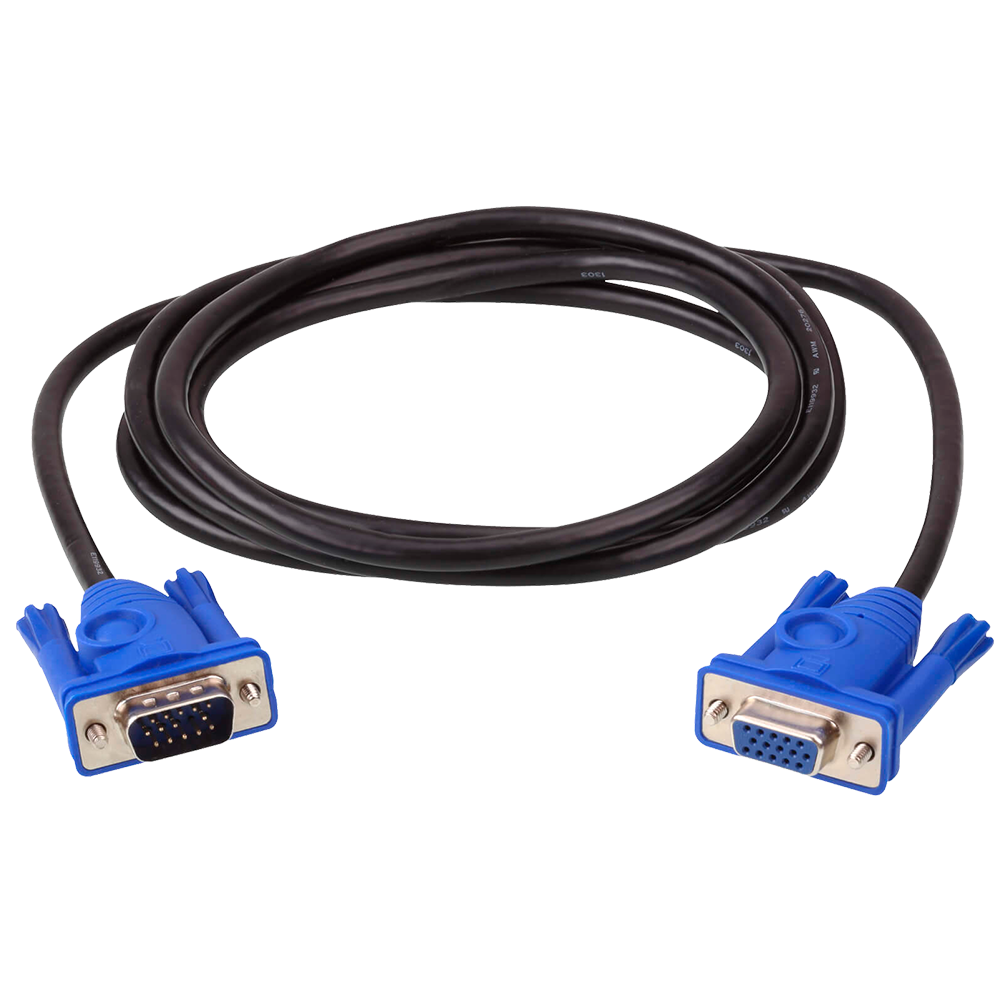
3M VGA Cable 2L2403, ATEN VGA Cables ATEN Corporate Headquarters
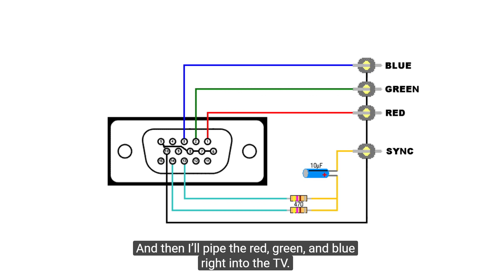
VGA DB15 connector pinout. The pin layout of the VGA interface connector is shown in the figure below. Three pins are used to carry the three basic RGB color signals red, green and blue and two pins carry the horizontal and vertical sync signal. The red, green and blue signal lines have their own ground return line.

14 Pin & 15 Pin VGA Cables & Their Uses Helpful Colin
2 4090's water looped, the rest must be pretty spicy. Every PSU should have the same outputs, so you can also reuse your nice custom cables you bought. I just use a tool and rejig the pins depending on the PSU, so i can reuse them. Not that spicy.. 32 core TR with 128 GB RAM. Kinda boring by todays standards.

Comprehensive Standard Series VGA Cable with Audio HD15PP6ST/A
VGA (Video Graphics Array/ Video Graphics Adapter) connector is one kind of computer port, used to connect the peripheral devices for transferring video signals as an output. It is a very famous standard display invented by IBM & launched in the year 1987. VGA Connector
VGA D15 Pinout Projection Design Bootcamp
Here is an ASCII pinout diagram for those who prefer it:. NOTE: If the optional +5V power output pin is used, a special DDC/VGA connector must be used to to provide proper sequencing. The +5V output voltage must be withing +/-5% range and tha card must be able to supply at least 300 mA current (maximum 1A).
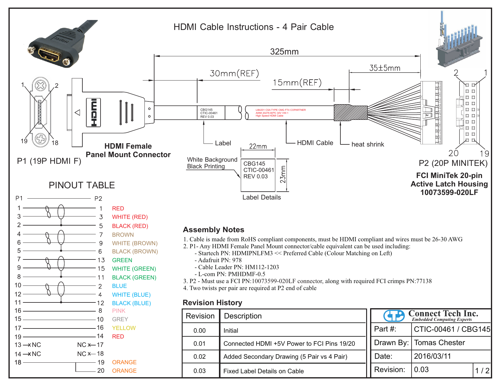
Bestio Vga To Hdmi Cable Wiring Diagram
What is a VGA Connector? One type of computer port is the VGA (Video Graphics Array/Video Graphics Adapter) connector, which has the ability to connect peripheral devices for sending video signals as an output. IBM created and introduced a well-known industry standard display in 1987.
VGA Pinout
Cable quality The same VGA cable can be used with a variety of supported VGA resolutions, ranging from 640×400px @70 Hz (24 MHz of signal bandwidth) to 1280×1024px (SXGA) @85 Hz (160 MHz) and up to 2048×1536px (QXGA) @85 Hz (388 MHz).
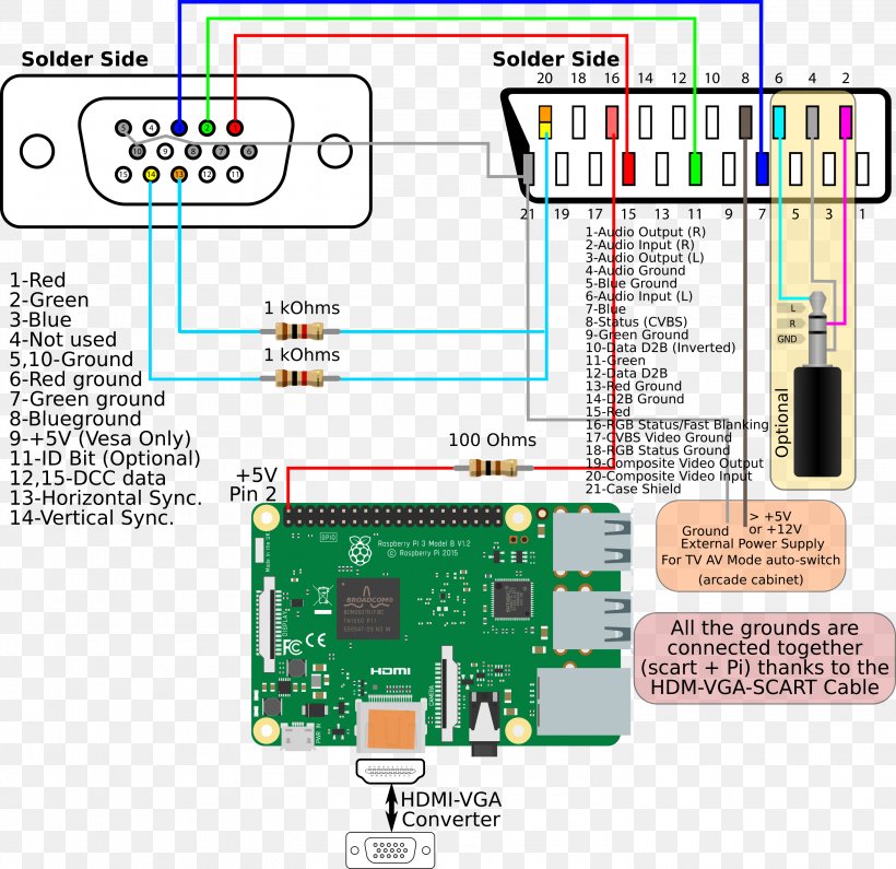
Rgb to vga converter circuit diagram plmshared
May 19, 2021 Tech Trends VGA is short for Video Graphics Array. It is a standard for video output that uses analog signals rather than digital signals. VGA connectors have 15 pins that each contribute to how the colors blend on the screen. The VGA standard was first introduced in 1987. IBM originally designed the standard for 640×480 displays.
triste engagement Betsy Trotwood vga cable pinout svelte hériter période
Wikipedia] The pinout diagram example "VGA connector pinout" was created using the ConceptDraw PRO diagramming and vector drawing software extended with the Audio and Video Connectors solution from the Engineering area of ConceptDraw Solution Park. Used Solutions Engineering > Audio and Video Connectors
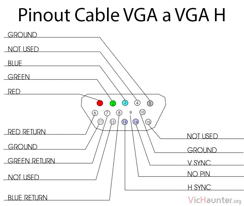
Qué es VGA_H y cómo hacerte un cable para enchufar tu monitor
If you look at the pinout for VGA, there are several ground pins: I was curious as to why, and I found this answer. To sum it up, the extra ground pins are so that each pin has its own ground in order to prevent interference in the analog signal. But here's a DVI-I connector that supports analog signals: The analog pins are on the right side.
DIY VGA to TV Cable Techwalla
VGA Cable Pinout is an essential component of many digital devices today. VGA cables are used to connect computers, displays, and other electronic devices to each other. VGA cables also enable audio signal as well as video signal transmission.
VGA Cable Gembrid Eslotparts
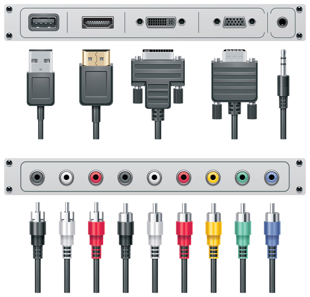
VGA is a connector that is used in various electronic devices to connect and transmit signals between monitors and computers, TVs and computers, and laptops and computers. It is used as a connector in various devices, including monitors, laptops, video cards, and televisions. This article has given you a general overview of the VGA connector.
VGA pinout diagram
The VGA connector pinout has been around for many years and is the standard analog computer video output. It's also an easy way to get sound from your computer speakers. But what are all those pins? A VGA connector is a 15-pin D-shaped plug with three rows of five pins.

DSub Cable / VGA Cable / Analog Signal EATECH TECHNOLOGY CO.
A video card (also called a video adapter) is an expansion card which generates a feed of output images to a display. Show device-specific * / Apple / ATI / Avermedia / Dell / Leadtek / Matrox / Nvidia pinouts only (please note that filtering may not be accurate) or follow to 49 OLD hardware pinouts.